Hi all, I am having a hard time understanding the basic underlying mechanism by which learning is done in Monty. Below is a description of my current understanding of how sensors work. Please let me know if I am on the right track.
(1) Sensors move across their environment and produce a sequence of observations. Each observation consists of a set of observed features (color, curvature, etc.) , the 3D coordinate of the features in the “world” reference frame, and the pose of the sensor relative to the sensors reference frame.
(2) Sensors also determine object boundaries. For each observation a sensor will produce a flag indicating if the observation was made on an object or not. My understanding is that the sensor uses data from the simulator to determine what is an object and what is the background.
Is this what is happening in the sensors (without getting into what the learning modules are doing)?
Regarding 2 above I don’t know how it is done, I just don’t think it is a correct way of doing it. It is the learning module task to tell whether the current sensor input (considering previous inputs and respective movements) matches some known object or not.
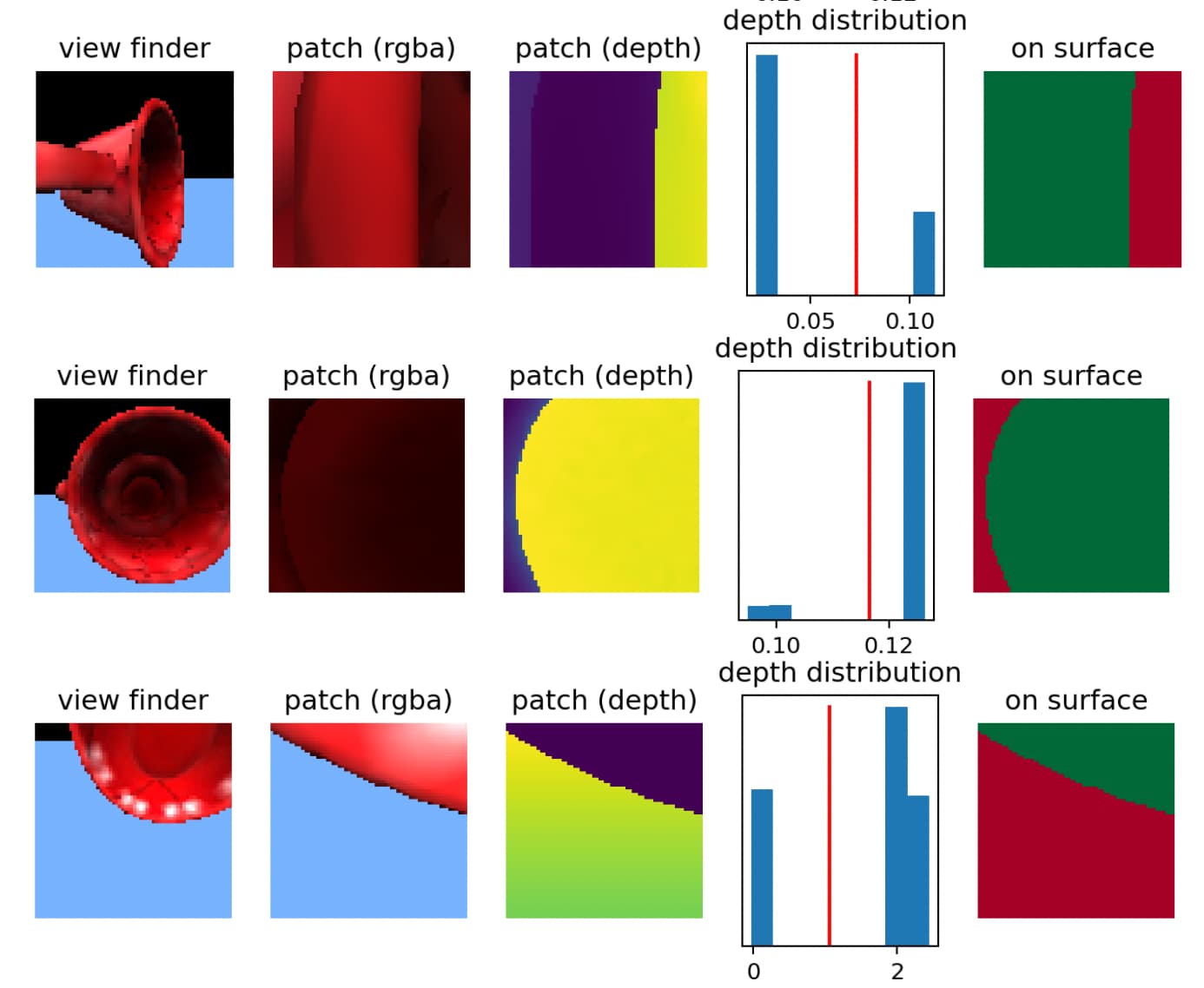
The current default setup is that we use the depth image to estimate which parts of the sensor patch are part of the object surface and which ones are not. The corresponding function is here: tbp.monty/src/tbp/monty/frameworks/environment_utils/transforms.py at 451ba5f576cfdf3eb1b14250d85125429b93d1e4 · thousandbrainsproject/tbp.monty · GitHub Other parts of the sensor patch may also be on the object (like imagine looking at the rim of a cup where you have the front surface of the mug in the foreground but you also see part of the inside of the mug) but we don’t want to use those pixels/depth values to estimate the principal curvature and point normal for the center of the patch. If we were to use all of them, it will introduce some noisy distortions. We are not using privileged information from the simulation for this; we are just applying some heuristics to the depth map.
Here are some examples of this:
(The viewfinder image is just to give you some context, the LM only sees the patch. We take the depth values in the patch and look at their distribution. If it is bimodal, we use this to set a cutoff point for which values are on or off object (green and red respectively on the right column of this figure)
There is some additional logic to decide which side of the distribution to use depending on where the center of the patch ends up.
We do have access to object labels from the simulator and sometimes extract those (like in multi object experiments) but they are only used for logging and evaluating performance. The learning module can not use this information to recognize objects.
Thanks @vclay for the detailed explanation. I have two follow up questions:
a) Besides being used to distinguish the object from the background, is the depth information also being used to compute the orthonormal vectors?
b) When we way that a sensor module “extracts features”, are we basically talking about this step where we apply the get_point_normal_* methods to the 3D surface shape detected in the patch?
a) yes, the depth information is combined with the sensor location to determine the location of the sensor patch. It is also used to estimate the orthonormal vectors.
b) Yes, estimating the point normal and principal curvature directions is part of what the sensor module is doing. Those three vectors are used to define the orientation of the sensor patch. Additionally, we can extract other features, such as the color at the center of the patch or the amount of curvature. These are just some basic examples of the features we extract right now. You could implement custom sensor modules that extract other features (like temperature, texture, or simple patterns).